The purpose of the Geographic Notice is to transmit information that pertains to a region or area, for example a security zone, an area of fog, or dredging operations. The areas that are being defined can be circles, rectangles, polygons, or sectors. They can also be defined as a simple point or series of points (polyline). The Geographic Notice message can be made up of multiple subareas in which case the total area is the union of the subareas. This message can also be used to convey advisory lines or tracks (using the polyline subarea); however, the Route Information message should be used for recommended or directed routes.
EU
Depending on the conditions
Timeout 3 times the duration / 30 minutes
Parameter | Bit | Description | ||
Message ID | 6 | Identifier for Message 8; always 8 | ||
Repeat Indicator | 2 | Used by the repeater to indicate how many times a message has been repeated. | ||
Source ID | 30 | MMSI number | ||
Spare | 2 | not used, should be set to zero, reserved for future use | ||
Binary data | Designated Area Code | 10 | DAC=200 | |
Function Identifier | 6 | FI=42 | ||
Version indicator | 3 | The version number of the message default = 0, rest for future use | ||
Spare | 3 | not used, should be set to zero, reserved for future use | ||
Message Linkage ID | 10 | A source specific running number, unique across all binary messages equipped with Message Linkage ID. Used to link additional information to the message by a Text Description message. The Message Linkage ID and the source MMSI uniquely identify the sent message. | ||
Notice Description | 7 | Notice Description as per Table 9. | ||
Start time of area | UTC month | 4 | UTC month of the Area start. | |
UTC day | 5 | UTC day of the Area start. | ||
UTC hour | 5 | UTC hour of the Area start. | ||
UTC minute | 6 | UTC minute of the Area start. | ||
Duration | 18 | Minutes until end of Geographic Notice, measured from start date and time of Geographic Notice. Maximum duration is 262.142 minutes (182.04 days). | ||
Action | 1 | Action parameter: | ||
Spare | 2 | not used, should be set to zero, reserved for future use. | ||
Sub-area 1 | 96 | Area description, structured as in | ||
Sub-area 2 | 96 | optional additional area, structured as in | ||
Sub-area 3 | 96 | optional additional area, structured as in | ||
Sub-area 4 | 96 | optional additional area, structured as in | ||
Sub-area 5 | 96 | optional additional area, structured as in | ||
Sub-area 6 | 96 | optional additional area, structured as in | ||
Sub-area 7 | 96 | optional additional area, structured as in | ||
Sub-area 8 | 96 | optional additional area, structured as in | ||
Sub-area 9 | 96 | optional additional area, structured as in | ||
Total | 216-984 | 2-5 slot message | ||
Number of sub-areas transmitted | 1 | 2 | 3 | 4 | 5 | 6 | 7 | 8 | 9 |
Number of bits used for a broadcast message | 216 | 312 | 408 | 504 | 600 | 696 | 792 | 888 | 984 |
Number of slots used for a broadcast message | 2 | 2 | 3 | 3 | 3 | 4 | 4 | 5 | 5 |
Number of bits used for an addressed message | 248 | 344 | 440 | 536 | 632 | 728 | 824 | 920 | 1016 |
Number of slots used for an addressed message | 2 | 2 | 3 | 3 | 4 | 4 | 5 | 5 | 5 |
Table 1: Number of sub-area transmitted
Value | Area Shape | Table for Definition |
0 | Circle, point or accurate polyline/polygon | 3 |
1 | Rectangle | 4 |
2 | Sector | 5 |
3 | Polyline | 6 |
4 | Polygon | 7 |
5 | Associated text | 8 |
6-7 | Reserved | -- |
Table 2: Sub-areas
| Parameter | # of bits | Description |
Geographic Notice: Sub-area shape 0 | Area Shape | 3 | Defines the shape of the area. |
Scale Factor | 2 | Scale factor. This is a multiplier for the dimensions of the shape. | |
Longitude | 28 | Longitude of the center in 1/10,000 minute (±180°). | |
Latitude | 27 | Latitude of the center in 1/10,000 minute (±90°). | |
Precision | 3 | Precision of the Lat/Long. Data to be truncated to the number of decimal places specified in this parameter. | |
Radius | 12 | Defines the size of the circular area. This is the radius of the circle in meter increments. | |
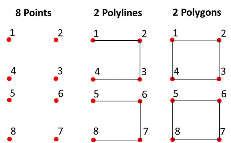
Link | 2 | Defines the possible link of the sub message[JvG4] [3] 0 = single point [J5] [4] / end point of polygon/polyline (default)[JvG6] [5] 1 = start/additional point of polyline 2 = start/additional point of polygone 3 = unused | |
Spare | 19 | .not used, should be set to zero, reserved for future use | |
| Total | 96 | 96 bit subarea |
Table 3: Circle or Polygon Point
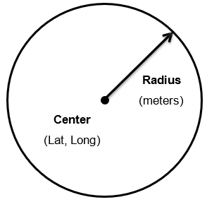
Figure 3: Circle diagram
Point | Link |
| Point | Link |
| Point | Link |
1 | 0 |
| 1 | 1 |
| 1 | 2 |
2 | 0 |
| 2 | 1 |
| 2 | 2 |
3 | 0 |
| 3 | 2 |
| 3 | 2 |
4 | 0 |
| 4 | 0 |
| 4 | 0 |
5 | 0 |
| 5 | 1 |
| 5 | 2 |
6 | 0 |
| 6 | 1 |
| 6 | 2 |
7 | 0 |
| 7 | 1 |
| 7 | 2 |
8 | 0 |
| 8 | 0 |
| 8 | 0 |
Figure 4: coding of point, polylines and polygons using circle sub-areas
| Parameter | # of bits | Description |
Geographic Notice: Sub-area shape 1 | Area Shape | 3 | Defines the shape of the area. |
Scale Factor | 2 | Scale factor. This is a multiplier for the dimensions of the shape. | |
Longitude | 28 | Longitude of the corner point*1 in 1/10,000 minute (±180°). | |
Latitude | 27 | Latitude of the corner point *1 in 1/10,000 minute (±90°). | |
Precision | 3 | Precision of the Lat/Long. Data to be truncated to the number of decimal places specified in this parameter. | |
E dimension | 8 | Box dimension East from the corner point in meter increments. This is multiplied by the scale factor to give a maximum dimension of 255,000m (255 km). | |
N dimension | 8 | Box dimension North from the corner point in meter steps. This is multiplied by the scale factor to give a maximum dimension of 255,000m (255 km). | |
Orientation | 9 | Rotation of area in degree steps. Area is rotated clockwise this number of degrees about the position above. | |
Spare | 8 | not used, should be set to zero, reserved for future use | |
| Total | 96 | 96 bit subarea |
Table 4: Rectangle or line or point
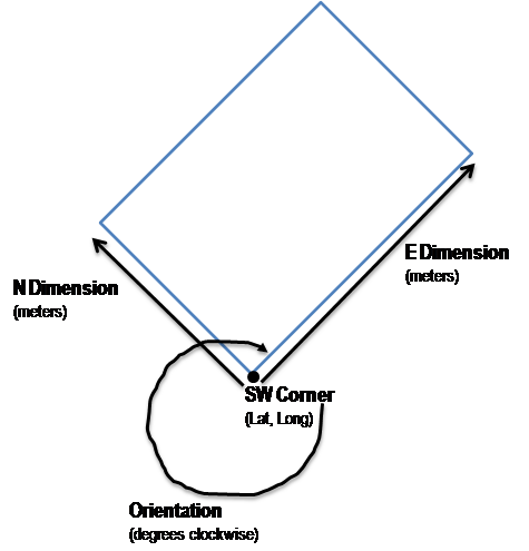
Figure 5: Rectangle diagram
| Parameter | # of bits | Description |
Geographic Notice: Sub-area shape 2 | Area Shape | 3 | Defines the shape of the area. |
Scale Factor | 2 | Scale factor. This is a multiplier for the dimensions of the shape. | |
Longitude | 28 | Longitude of the center in 1/10,000 minute (±180°). | |
Latitude | 27 | Latitude of the center in 1/10,000 minute (±90°). | |
Precision | 3 | Precision of the Lat/Long. Data to be truncated to the number of decimal places specified in this parameter. | |
Radius | 12 | Defines the size of the sector. This is the radius of the sector in meter increments. | |
Left boundary | 9 | Orientation of the left boundary edge of the sector. This is in degree steps measured clockwise from true North about the center point. | |
Right boundary | 9 | Orientation of the right boundary edge of the sector. This is in degree steps measured clockwise from true North about the center point. Total sector area is the area measured from the left boundary clockwise to the right boundary. | |
Spare | 3 | not used, should be set to zero, reserved for future use | |
| Total | 96 | 96 bit subarea |
Table 5: Sector

Figure 6: Sector description. a) Center point, b) Sector radius, c) Sector bearings from center point, left boundary, d) Sector bearings from center point, right boundary
| Parameter | # of bits | Description |
Geographic Notice: Sub-area shape 3 (polyline) or 4 (polygon) | Area Shape | 3 | Defines the shape of the area. Set to 3 for Polyline (open area or line) or set to 4 for Polygon (closed area). The initial point (point 0) is defined by an Area Shape = 0 (Circle, point or accurate polyline/polygon). Or could be added to a previous Polyline/Polygon To close the polygon shape, connect the last defined point back to the initial point (Point 0). |
Scale Factor | 2 | Scale factor. This is a multiplier for the dimensions of the shape. | |
Point 1 Angle | 10 | True bearing (in half-degree steps) from Point 0 to Point 1 or from the last Point in a Polyline/Polygon directly preceding this Polyline/Polygon to Point 1 in this Polyline/Polygon. | |
Point 1 distance | 11 | Distance (in meters) from Point 0 or from the last Point in a Polyline/Polygon directly preceding this Polyline/Polygon to Point 1 in this Polyline/Polygon. Multiply by the scale factor to give a maximum of 2.047m (2,047 km). | |
Point 2 Angle | 10 | True bearing (in half-degree steps) from Point 1 to Point 2 | |
Point 2 distance | 11 | Distance (in meters) from Point 1 to Point 2. Multiply by the scale factor to give a maximum of 2.047m (2,047 km). | |
Point 3 Angle | 10 | True bearing (in half-degree steps) from Point 2 to Point 3 | |
Point 3 distance | 11 | Distance (in meters) from Point 2 to Point 3. Multiply by the scale factor to give a maximum of 2.047m (2,047 km). | |
Point 4 Angle | 10 | True bearing (in half-degree steps) from Point 3 to Point 4 | |
Point 4 distance | 11 | Distance (in meters) from Point 3 to Point 4. Multiply by the scale factor to give a maximum of 2.047m (2,047 km). | |
Link | 2 | Defines the possible link of the sub message 0 = single polyline/polygon and/or end point of polygon/polyline (default) 1 = start/additional point of polyline 2 = start/additional point of polygon 3 = unused | |
Spare | 5 | not used, should be set to zero, reserved for future use | |
| Total | 96 | 96 bit subarea |
Table 6: Polyline
Examples of a single polyline (Area Shape = 3, Link = 0)
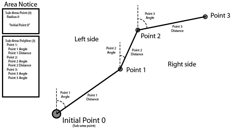
Figure 7: Graphic description of a waypoint/polyline, showing angle and distance between points. If one side of a polyline is to be a boundary (e.g., edge of ice area), this is defined by the left side of the line in order of sequence from the initial sub-area point (Point 0)
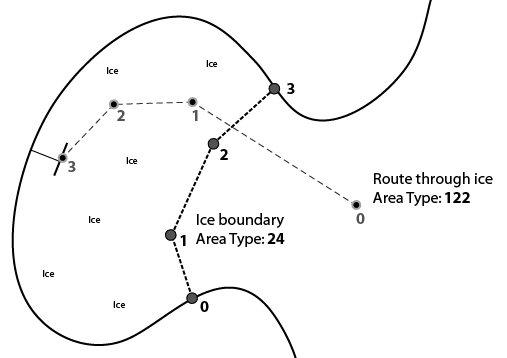
Figure 8: Graphic depiction of: 1) ice boundary between sea ice and open water, and 2) recommended route through the sea ice area
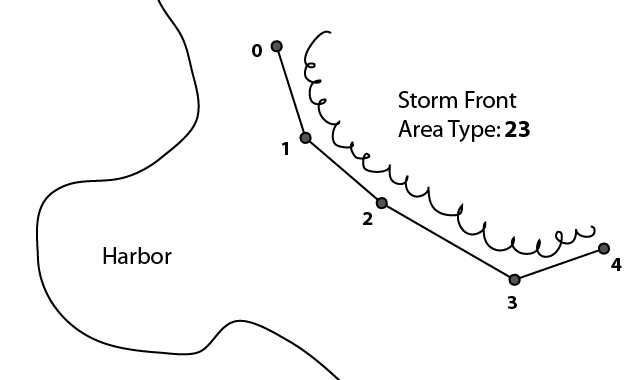
Figure 9: A graphic depiction of a storm front message
| Parameter | # of bits | Description |
Geographic Notice: Sub-area | Area Shape | 3 | Defines the shape of the area. Set to 5 for Associated Text. |
Text | 90 | Fifteen 6-bit ASCII characters, 6 bit ASCII characters as per Table 44 in ITU | |
Spare | 3 | not used, should be set to zero, reserved for future use | |
| Total | 96 | 96 bit subarea |
Table 8: Associated Text
Value | Description |
0 | Caution: Marine mammal habitat |
1 | Caution: Marine mammals in area - reduce speed |
2 | Caution: Marine mammals in area - stay clear |
3 | Caution: Marine mammals in area - report sightings |
4 | Caution: Protected Habitat - reduce speed |
5 | Caution: Protected habitat - stay clear |
6 | Caution: Protected habitat - no fishing or anchoring |
7 | Caution: Derelicts (drifting objects) |
8 | Caution: Traffic congestion |
9 | Caution: Marine event or regatta |
10 | Caution: Divers down |
11 | Caution: Swim area |
12 | Caution: Dredge operations |
13 | Caution: Survey operations |
14 | Caution: Underwater operation |
15 | Caution: Seaplane operations |
16 | Caution: Fishery - nets in water |
17 | Caution: Cluster of fishing vessels |
18 | Caution: Fairway closed |
19 | Caution: Harbor closed |
20 | Caution: Submerged pipeline or cable |
21 | Caution: Unmanned vehicle operation |
22 | Caution: other (define in associated text field) |
23 | Environmental Caution: Storm front (line squall) |
24 | Environmental Caution: Hazardous sea ice i.e. icebergs and growlers |
25 | Environmental Caution: Storm warning (storm cell or line of storms) |
26 | Environmental Caution: High wind |
27 | Environmental Caution: High waves |
28 | Environmental Caution: Restricted visibility (fog, rain, etc) |
29 | Environmental Caution: Strong currents |
30 | Environmental Caution: Heavy icing |
31 | Environmental Caution: Oil or other hazardous substance in area |
32 | Environmental Caution: other (define in associated text field) |
33 | Restriction: Fishing prohibited |
34 | Restriction: Entry approval required prior to transit |
35 | Restriction: Entry prohibited |
36 | Restriction: Active military OPAREA |
37 | Restriction: Firing - danger area |
38 | Restriction: Drifting mines |
39 | Restriction: other (define in associated text field) |
40 | Anchorage: Anchorage open |
41 | Anchorage: Anchorage closed |
42 | Anchorage: Anchoring prohibited |
43 | Anchorage: Deep draft anchorage |
44 | Anchorage: Shallow draft anchorage |
45 | Anchorage: Vessel transfer operations |
46 | Anchorage: other (define in associated text field) |
47 | Ice Report: Ice Edge |
48 | Ice Report: New Ice (<10cm ocean <5cm lake) |
49 | Ice Report: Young Ice (10-30cm) |
50 | Ice Report: Thin 1st year ice (30-70cm ocean, 5-15cm lake) |
51 | Ice Report: Medium 1st year ice (70-120cm ocean, 15-30cm lake) |
52 | Ice Report: Thick 1st year ice (120-200 cm ocean, 30-70cm lake) |
53 | Ice Report: Old /very thick ice (>200cm ocean, >70cm lake) |
54 | Ice Report: Undetermined or unknown thickness |
55 | Reserved for Future Use |
56 | Security Alert - Implement USA MARSEC Level 1 |
57 | Security Alert - Implement USA MARSEC Level 2 |
58 | Security Alert - Implement USA MARSEC Level 3 |
59 | Reserved for Future Use |
60 | Reserved for Future Use |
61 | Reserved for Future Use |
62 | Reserved for Future Use |
63 | Reserved for Future Use |
64 | Distress: Vessel disabled and adrift |
65 | Distress: Vessel sinking |
66 | Distress: Vessel abandoning ship |
67 | Distress: Vessel requests medical assistance |
68 | Distress: Vessel flooding |
69 | Distress: Vessel fire/explosion |
70 | Distress: Vessel grounding |
71 | Distress: Vessel collision |
72 | Distress: Vessel listing/capsizing |
73 | Distress: Vessel under assault |
74 | Distress: Person overboard |
75 | Distress: SAR area |
76 | Distress: Pollution response area |
77 | Distress: other (define in associated text field) |
78 | Reserved for Future Use |
79 | Reserved for Future Use |
80 | Instruction: Contact VTS at this point/juncture |
81 | Instruction: Contact Port Administration at this point/juncture |
82 | Instruction: Do not proceed beyond this point/juncture |
83 | Instruction: Await instructions prior to proceeding beyond this point/juncture |
84 | Instruction: Proceed to this location – await instructions |
85 | Instruction: Clearance granted – proceed to berth/lock |
86 | Instruction: other (define in associated text field) |
87 | Reserved for Future Use |
88 | Information: Pilot boarding position |
89 | Information: Icebreaker waiting area |
90 | Information: Places of refuge |
91 | Information: Position of icebreakers |
92 | Information: Location of response units |
93 | Information: VTS active target |
94 | Information: Rogue or suspicious vessel |
95 | Information: Vessel requesting non-distress assistance |
96 | Information: other (define in associated text field) |
97 | Chart Feature: Submerged object / sunken vessel (describe in associated text field) |
98 | Chart Feature: Semi-submerged object |
99 | Chart Feature: Shoal area |
100 | Chart Feature: Shoal area due north |
101 | Chart Feature: Shoal area due east |
102 | Chart Feature: Shoal area due south |
103 | Chart Feature: Shoal area due west |
104 | Chart Feature: Channel obstruction |
105 | Chart Feature: Reduced vertical clearance |
106 | Chart Feature: Bridge/Gate/Lock/other closed |
107 | Chart Feature: Bridge/Gate/Lock/other partially open (opening) |
108 | Chart Feature: Bridge/Gate/Lock/other fully open |
109 | Chart Feature: Bridge/Gate/Lock/other partially closed (closing) |
110 | Chart Feature: Bridge/Gate/Lock/AtoN/other inoperative or not working properly |
111 | Chart Feature: other (define in associated text field) |
112 | Report from ship: Icing info |
113 | Report from ship: Intended route |
114 | Report from ship: other (define in associated text field) |
115 | Reserved for Future Use |
116 | Reserved for Future Use |
117 | Reserved for Future Use |
118 | Reserved for Future Use |
119 | Reserved for Future Use |
120 | Route: Recommended Route |
121 | Route: Alternative Route |
122 | Route: Recommended Route through ice |
123 | Route: other (define in associated text field) |
124 | Reserved for Future Use |
125 | Other – Define in associated text field |
126 | Cancellation – cancel area as identified by Message Linkage ID |
127 | Undefined (default) |
Table 9: Notice Description
Links
[1] file://nas/Data1/ASM/20200311_Draft_VTT_EG_Inventory_of_Inland_ASM_Ed-1.48.docx#_msocom_2
[2] file://nas/Data1/ASM/20200311_Draft_VTT_EG_Inventory_of_Inland_ASM_Ed-1.48.docx#_msocom_3
[3] file://nas/Data1/ASM/20200311_Draft_VTT_EG_Inventory_of_Inland_ASM_Ed-1.48.docx#_msocom_4
[4] file://nas/Data1/ASM/20200311_Draft_VTT_EG_Inventory_of_Inland_ASM_Ed-1.48.docx#_msocom_5
[5] file://nas/Data1/ASM/20200311_Draft_VTT_EG_Inventory_of_Inland_ASM_Ed-1.48.docx#_msocom_6
[6] file://nas/Data1/ASM/20200311_Draft_VTT_EG_Inventory_of_Inland_ASM_Ed-1.48.docx#_msocom_1